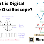
- Sampling Oscilloscope Definition: A sampling oscilloscope is defined as an advanced type of digital oscilloscope designed to sample high-frequency waveforms by capturing multiple data points.
- Functioning of Sampling Oscilloscope: It operates by collecting samples from successive waveforms and reconstructing the complete waveform for display, useful for observing fast electrical signals.
- Sampling Methods: There are two primary sampling methods: real-time sampling, which captures transient events, and equivalent sampling, which works with repetitive waveforms.
- Real-Time Sample Method: This method captures high-frequency transient events in one sweep, requiring high-speed memory to store the data.
- Equivalent Sample Method: This method relies on repetitive waveforms, using either random or sequential sampling to improve accuracy in signal capture.
A sampling oscilloscope is an equivalent-time instrument for measuring fast, repetitive signals. All digital oscilloscopes take samples, but the name “sampling oscilloscope” usually refers to an instrument that builds one displayed waveform from samples taken after many trigger events. A real-time oscilloscope instead captures a continuous record during one acquisition.
The input must repeat with stable timing and shape because samples from different cycles are treated as points on the same waveform. The instrument changes or measures each sample’s delay relative to the trigger, then places the samples on an equivalent-time axis. Required point count depends on the waveform, measurement, time span and interpolation; there is no universal 1,000-point rule.
How a Sampling Oscilloscope Works
The trigger provides a repeatable timing reference. A high-bandwidth sampling gate captures a small portion of the input on each recognised event. A hold circuit and lower-bandwidth electronics then measure that sample. The acquisition system stores the value with its trigger-relative time and reconstructs the display. Reconstruction or a digital band pass filter may shape the displayed response, but it does not restore information that the analogue sampler failed to capture.
Each displayed point has a measured amplitude and an assigned time relative to the trigger. The effective sample interval can be much smaller than the physical interval between acquisitions because the points come from different repetitions. This creates a high equivalent sample rate, not a high single-shot acquisition rate. Analogue bandwidth is set by the sampler, input network and interconnects. Bandwidth, dynamic range, noise, timing accuracy and maximum input level are model-specific specifications.
Wide-band sampling heads often accept a smaller voltage range than general-purpose real-time inputs and may be vulnerable to overload. Sampling oscilloscopes cannot preserve a one-time event because each displayed record combines multiple triggers. They work well for repetitive pulses, clock waveforms, impulse responses and eye diagrams when the trigger and signal satisfy the instrument requirements.
Sampling Methods
In a traditional sequential sampler, a trigger starts a calibrated delay ramp or timing oscillator. A comparator generates the sampling command when the timing ramp reaches the selected delay. The sampling gate then captures the instantaneous input voltages. Incrementing the delay moves successive samples across the time window. Modern implementations vary, but the central distinction remains between real-time acquisition from one trigger and equivalent-time reconstruction from repeated triggers.
Real-Time Sampling
A real-time oscilloscope takes a continuous sequence of samples after one trigger. It can therefore capture repetitive waveforms, unstable behaviour and single-shot transients. The analogue bandwidth and sample rate must be high enough for the signal components being measured, while memory depth determines the available time span at a chosen rate. Modern rates are expressed in samples per second and vary widely by instrument; the former 500 MHz and 100-sample-per-second figures were inconsistent.
Equivalent-Time Sampling
Equivalent-time sampling does not predict an unknown waveform. It assumes that successive repetitions are equivalent within the required accuracy. The digitizer collects one or more points during each acquisition and combines their trigger-relative times into one record. This can provide fine timing resolution for a repetitive signal even when physical acquisitions occur much more slowly. Trigger jitter, pattern variation and drift appear as measurement error. The two common forms are random and sequential sampling.
Random Equivalent-Time Sampling
In random equivalent-time sampling, the sampling clock runs asynchronously with the input signal and trigger. The instrument measures the interval between each sample and its associated trigger, then places the point at that time in the reconstructed record. Samples are regular in acquisition time but random relative to the trigger. This method can collect points on both sides of the trigger and may take more than one sample per event.
Sequential Equivalent-Time Sampling
In sequential equivalent-time sampling, the instrument normally takes one sample after each recognised trigger. The first sample occurs after a known delay. For the next trigger, the delay increases by a small interval, and the process repeats until the selected time window is filled. Samples therefore appear from left to right in sequence. The signal must repeat long enough to acquire the record, and pre-trigger information needs a suitable external trigger or delay arrangement.