

- Cutoff Frequency Defined: Cutoff frequency is defined as the point in a frequency response at which the signal begins to be attenuated rather than fully passing through.
- Formula and Calculation: The cutoff frequency is calculated by taking 1 divided by the product of two times pi, the resistance, and the capacitance. This shows how the frequency at which the output signal power is halved is directly influenced by the resistance and capacitance values.
- Understanding Bandwidth: Bandwidth is the difference between the upper and lower cutoff frequencies, crucial for applications like audio processing where a flat response is desired.
- Decibel Significance: Gain in circuits is expressed in decibels, a logarithmic unit that matches the human ear’s response, important for understanding signal amplification and attenuation.
- Method of Finding: Cutoff frequency can be calculated using transfer functions or visualized on Bode plots, aiding in the design and analysis of electrical filters.
What is Cutoff Frequency?
Cutoff frequency, also called corner frequency or break frequency, is a boundary in a system’s frequency response. At that frequency, energy through the system starts to be reduced or reflected instead of passing at the passband level.
In electronics, the cutoff frequency is the frequency above or below which the power output of a circuit such as a line, amplifier or electronic filter (for example a high pass filter) has fallen to a stated fraction of the passband power.
That fraction is usually one half of the passband power. A 3 dB drop is close to half power (exactly 10 log10(0.5) is about -3.01 dB). As a voltage ratio, the same point is a fall to 1/sqrt(2), about 0.707 of the passband voltage.
For filter circuits such as RC circuits, the cutoff frequency marks where attenuation begins to rise quickly with frequency.
The usable band of an amplifier gain curve is the frequency range where gain stays within 70.7% of the mid-frequency maximum. On the curve below, f1 is the lower cutoff and f2 is the upper cutoff.
What is Bandwidth?
In signal processing, bandwidth is the difference between the upper cutoff frequency and the lower cutoff frequency. f2 sits in the high-frequency range and f1 in the low-frequency range. Those two points are also called half-power frequencies because voltage gain drops to 70.7 % of the maximum value.
That voltage drop matches one half of the power at the midband reference frequency. Teaching plots treat the midband from f1 to f2 as flat when the gain change stays inside that half-power window.

Cutoff Frequency Formula
For a first-order RC filter, the cutoff frequency (corner frequency) is

where R and C are the values of Resistance and Capacitance. For a simple RC low pass filter, that 3 dB point occurs when the resistance has the same magnitude as the capacitive reactance.
Decibel Unit
Gain is often stated in decibels. The decibel is a logarithmic measure of a power ratio or a voltage ratio.
Voltage gain of an amplifier in decibels is  .
.
Power gain of the amplifier in decibels is 
When Av is greater than one, the dB gain is positive and the circuit amplifies. When Av is less than one, the dB value is negative and the circuit attenuates.
Some plots set midband amplifier gain to a 0 dB reference so other frequencies can be compared with that baseline.
Amplifiers show their highest gain in the mid-frequency range. That midband maximum is often plotted as 0 dB. Gain below that midband value is then a negative dB number.
How to Find Cutoff Frequency
Cutoff frequency can be read from a transfer function or from a Bode plot.
Cutoff Frequency from Transfer Function
A transfer function describes how a circuit responds as the sinusoidal source frequency changes. It is the ratio of output voltage to input voltage, written in the s domain.
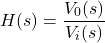
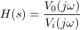
For a sinusoidal source, the same function gives the magnitude and phase of the output voltage relative to the input. In that case  replaces s.
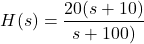
For example, consider the transfer function
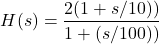
To read the corner frequencies, rewrite H(s) in this factored form:
(1) 
(2) 
From that form the corner frequencies are  and
and  . The frequency axis for a Bode sketch is chosen around those two values.
Cutoff Frequency from Bode Plot
Control engineers use this graph to judge stability. It has two parts: a Bode magnitude plot of response in decibels and a phase plot of phase shift in degrees.
On a Bode plot, the corner frequency is the frequency where the two straight-line asymptotes meet.
The transfer function  of a system carries the gain and stability data of the system. Bode plots give an estimated picture of a given
 from which the gain of the system and its stability properties can be
read.

Cutoff Frequency of a Low Pass Filter
A low-pass filter passes low-frequency signals and reduces high-frequency signals. Its cutoff frequency is the point where output voltage falls to 70.7% of the low-frequency (near 0 Hz) output, a 3 dB drop from that reference.

For example, if a low pass capacitive filter has  and
and  , at what frequency is the output 70.7% of the low-frequency output?
A simple capacitive low pass filter with one resistor and one capacitor has a cutoff frequency of  . Substituting those R and C values gives 45.473 Hz. The output is then 70.7% of the low-frequency output at 45.473 Hz.
When a Bode plot is drawn for a low pass filter as shown in the image below, the frequency response stays nearly flat at low frequencies.
Until the cutoff frequency is reached, the input is passed to the output with a gain near 1. That happens because the capacitor reactance is large at low frequencies and little current flows through the capacitor. After the cutoff, the first-order response falls at about -20 dB/decade.
The frequency at which capacitive reactance equals resistance is the cutoff frequency of this low-pass filter. At that frequency the output voltage is 70.7% of the low-frequency output, or -3dB relative to that reference.
Consider a first-order low pass filter with this transfer function:
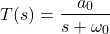
Rewrite the equation by dividing the numerator and denominator by RC:
(3) 
(4) 
Hence  and
and  , where
  is the angular cutoff frequency.
To see the cutoff on the frequency axis, convert the s-domain transfer function to form.

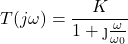
Now evaluate this expression at the cutoff frequency:

The denominator is a complex number, so the magnitude must be calculated.

K is the DC gain. When the input frequency reaches the cutoff frequency, the output amplitude is  . The factor
  is -3 dB, which is the cutoff definition used here.
The transfer-function result is the same statement in algebra: cutoff is the frequency where the filter amplitude is 3 dB below the very-low-frequency amplitude.
Cutoff Frequency of a High Pass Filter
A high-pass filter passes signals above a stated cutoff frequency. It reduces signals below that cutoff frequency.

The transfer function is derived in the equations below.

The output impedance is given as

Input impedance is given as

The transfer function of a high pass filter is the ratio of output voltage to input voltage.


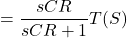

Compare that result with the standard high-pass form:
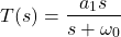
 is the high-frequency gain of the signal
 is the angular cutoff frequency
The cutoff frequency is the boundary between the passband and the stopband. For a high pass filter, a signal above that frequency is passed. The first-order high-pass cutoff equation is the same as the first-order low-pass equation.
Cutoff Frequency of a Bandpass Filter
The Band Pass Filter has two cutoff frequencies. It is made from a high-pass stage and a low-pass stage. The first formula below is labelled FC high. That upper edge is set by the low-pass stage.


The second formula below is labelled FC low. That lower edge is set by the high-pass stage.

Bandwidth is the span between those two frequencies. The high-pass cutoff is the lower edge of the band. The low-pass cutoff is the upper edge of the band.
Cut off Frequency of RL circuit
Consider a simple RL circuit as shown below.

The transfer function is
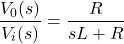
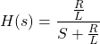
Substitute  to obtain the frequency response:
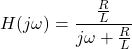
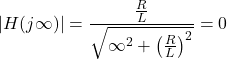
Magnitude Response is

When  = 0
= 0
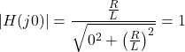
When = 
To calculate the cutoff frequency,

The cutoff frequency of this RL circuit is


Cut off Frequency of RC circuit
Consider a simple RC circuit as shown below.

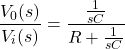
The transfer function is
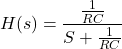
Substitute to obtain the frequency response:
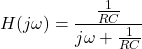
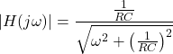
Magnitude Response is
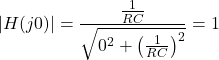
When = 0
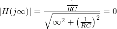
When =
To calculate the cutoff frequency,

The cutoff frequency of this RC circuit is


