

- CRO Definition: A Cathode Ray Oscilloscope (CRO) is defined as an electronic device used to analyze the voltage waveforms of different signals.
- Lissajous Patterns Definition: Lissajous patterns in CRO are the shapes formed on the CRO screen when sinusoidal voltages are applied to its deflection plates.
- Phase Difference Analysis: The phase difference between two sinusoidal signals of the same frequency is determined using the shape of Lissajous patterns.
- Frequency Ratio Calculation: The ratio of frequencies of signals applied to the CRO’s deflection plates is found by counting the tangencies of the Lissajous pattern.
- Ellipse Patterns: Lissajous patterns form ellipses that change shape depending on the phase difference and the quadrant through which the major axis passes.
Cathode Ray Oscilloscope (CRO) is very important electronic device. CRO is very useful to analyze the voltage wave form of different signals. The main part of CRO is CRT (Cathode Ray Tube). A simple CRT is shown in figure below-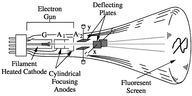
When the horizontal and vertical deflection plates of a CRO (Cathode Ray Oscilloscope) are connected to two sinusoidal voltages, the patterns that appear on the screen are called Lissajous pattern.
Shape of these Lissajous pattern changes with changes of phase difference between signal and ration of frequencies applied to the deflection plates (traces) of CRO. Which makes these Lissajous patterns very useful to analysis the signals applied to deflection plated of CRO. These lissajous patterns have two Applications to analysis the signals. To calculate the phase difference between two sinusoidal signals having same frequency. To determine the ratio frequencies of sinusoidal signals applied to the vertical and horizontal deflecting plates.
Calculation of the phase difference between two Sinusoidal Signals having same frequency
When two sinusoidal signals of same frequency and magnitude are applied two both pairs of deflecting plates of CRO, the Lissajous pattern changes with change of phase difference between signals applied to the CRO.
For different value of phase differences, the shape of Lissajous patterns is shown in figure below,
| SL No. | Phase angle difference ‘ø’ | Lissajous Pattern appeared at CRO Screen |
| 1 | 0o & 360o | 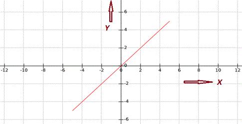 |
| 2 | 30o or 330o |  |
| 3 | 45o or 315o |  |
| 4 | 60o or 300o |  |
| 5 | 90o or 270o |  |
| 6 | 120o or 240o | 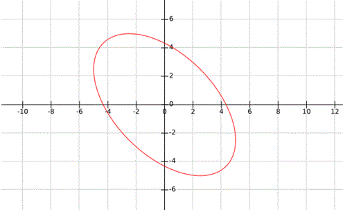 |
| 7 | 150o or 210o |  |
| 8 | 180o |  |
There are two cases to determine the phase difference ø between two signals applied to the horizontal and vertical plates,
Case – I: When, 0 < ø < 90o or 270o < ø < 360o : –
As we studied above it clear that when the angle is in the range of 0 < ø < 90o or 270o < ø < 360o, the Lissajous pattern is of the shape of Ellipse having major axis passing through origin from first quadrant to third quadrant:
Let’s consider an example for 0 < ø < 90o or 270o < ø < 360o, as shown in figure below,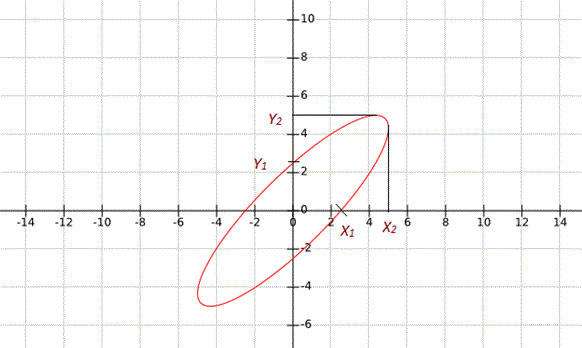
In this condition the phase difference will be,
Another possibility of phase difference,
From Above given Lissajous pattern 

Another Possibility of Phase Difference, 
Case – II: When 90o < ø < 180o or 180o < ø < 270o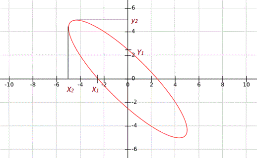
As we studied above it Clear that when the angle is in the range of 0o < ø < 90o or 270o < ø < 360o, the Lissajous Pattern is of the shape of Ellipse having major axis passing through origin from second quadrant to fourth quadrant:
Let’s consider an example for When, 90o < ø < 180o or 180o < ø < 270o, as shown in figure below,
In this condition the phase difference will be, 
Another possibility of phase difference,
From Above given Lissajous pattern 

Another Possibility of Phase Difference, 
To determine the ratio of frequencies of signal applied to the vertical and horizontal deflecting plates:
To determine the ratio of frequencies of signal by using the Lissajous pattern, simply draw arbitrary horizontal and vertical line on lissajous pattern intersecting the Lissajous pattern. Now count the number of horizontal and vertical tangencies by Lissajous pattern with these horizontal and vertical line.
Then the ratio of frequencies of signals applied to deflection plates,
Or,
Let consider some example to clear the concept in details:
Examples Lissajous Pattern
| Sl No. | Lissajous Pattern | Ratio of Frequencies fy/fx |
| 1 | 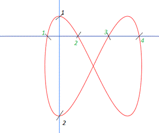 | fy/fx = 4/2 = 2 |
| 2 |  | fy/fx = 3/1 = 3 |
| 3 | 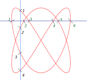 | fy/fx = 6/4 = 3/2 |
| 4 |  | fy/fx = 6/8 = 3/4 |
| 5 | 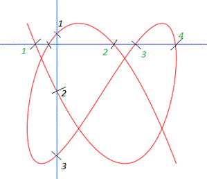 | fy/fx = 4/3 |


